
Design with RACE – Guide
RACE Software Overview
RACE (Rapid Axle Concept Evolution) is a cloud based multibody simulation (MBS) / multibody dynamics (MBD) software for the development of suspension systems.
At RACE Software we believe the value add in any simulation and analysis activity comes from the time spent analysing results and deciding on the next design iteration. Time spent on model build, debug, parameterisation, post-processing, etc. does not improve your design, it is essential non-value add. RACE has been developed to minimise the time spent on these non-value add activities during the development of automotive and motorsport suspension systems.
RACE requires user inputs in the form of suspension hardpoints, joint types and wheel and tyre dimensions. Once complete the user submits the inputs to a dedicated cloud server for analysis. The server runs Kinematics and Compliance (K&C) simulations in which vertical, roll, cornering, steering, aligning torque, traction and braking loads are applied to the suspension system and the response of the system to each is recorded. Once complete RACE generates reports ( Pdf and raw CSV) to show the performance of the suspension against over 50 Key performance indicators (KPIs). The reports are then uploaded to the users account for review.
RACE Software currently has two different levels to cater for different use cases and user needs.
- RACE Standard is the recommended starting point for any suspension design. It aims to minimise the user input required to run an analysis while still giving a detailed and comprehensive Suspension Key Performance Indicator (KPI) report. It therefore enables rapid iteration to get to a feasible design concept. To achieve this, the focus is put on the key inputs required for the model build while assumptions are made for parameters which have a lesser impact on the suspension performance.
- RACE Advanced adds additional complexity to the model in the form of nonlinear bushes and an anti-roll bar. It allows the user to change the ride height at which the analysis is run, set static toe and camber and customise the test events. It also runs an opposite wheel travel event (roll event). It therefore allows greater customisation of the model and analysis but requires more detailed user inputs.
Both RACE Standard and Advanced level accounts come with preloaded demo simulations for all suspension types for the user to import them quickly and make changes to their desired design, for ease of use.
To get a glimpse of the RACE Software reports download here a PDF Demo STANDARD Report – Double Wishbone Suspension and here a PDF Demo ADVANCED Report – Double Wishbone Suspension. Besides the PDF Reports users will get raw CSV data outputs for further analysis and results interpretation for KPIs, KnC outputs and nonlinear bushes / joins (Advanced only).
For RACE Software Updates / Change Log please CLICK HERE.
This guide walks the user through the different sections of the input template which the user must complete to run an analysis in RACE. The first step is navigate to the ‘Run a simulation’ page on the RACE platform and select the suspension type you would like to simulate. This opens a new simulation template for your chosen suspension type.
At the bottom of the page you shall find quick explainer videos of both RACE Software Standard and Advanced levels.
Loading Previous Inputs
Inputs can be loaded from a previously run simulation or suspension hardpoints can be loaded from a csv file. To load from a previously run simulation, click ‘load from a previous simulation’. This brings you to the previous simulations page. Find the simulation you would like to load and click ‘Load’. This populates a new simulation with a copy of the previous simulation inputs.
To load a csv file containing suspension hardpoints, first choose the file you want to load by clicking the ‘choose file’ button. Then click ‘Load hardpoints from the selected csv file’. If the load is successful, you will get a message saying ‘Success: csv file uploaded and hardpoint input fields updated’.
The CSV file should have one hardpoint per line in the format: hardpoint, x-coordinate, y-coordinate, z-coordinate. The csv example below loads three hardpoints for P3, P4 and P6:
3, 50, -400, 305
4, 100, -400, 300
6, 100, -700, 280
Inputting Suspension Hardpoints
The hardpoints must be entered in the RACE Software coordinate system. The X-axis points towards the rear of the vehicle, the Y-axis points to the right of the vehicle and the Z-axis points upwards. The vehicle centre line is at Y = 0. The axis system is shown below:
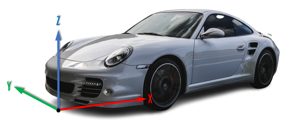
Figure 1. RACE Software Vehicle X,Y,Z Coordinate System
Each suspension template uses a suspension hardpoint numbering convention to simplify the naming of the different hardpoints in the system. The hardpoint numbering convention is defined for each suspension type in the user input template as shown in the example below for a double wishbone suspension.

Figure 2. RACE Software Standard – Double Wishbone Suspension Hardpoint Numbering
Inputting Joint Parameters
In RACE Standard the joint types can be defined by selecting the appropriate stiffness for each joint in the suspension using the drop down boxes. The joint rate (or stiffness) terminology used in RACE is shown are in the diagram below.

Figure 3. RACE Software – Bush/Joint Diagram – Radial, Axial, Conical, Torsional Stiffness Directions
RACE Standard has a pre-populated set of joint options, these include standard bushes, compliance bushes, ball bushes and ball joints.
- Standard bushes are typical automotive bush joints. They can be specified with a range of radial rates from 2kN/mm to 20 kN/mm. Joints of this type typically have axial rates which are much lower than the radial rate. Standard bushes also have generic conical and torsional rates which cannot be changed in RACE Standard. The conical rate is 500 Nm/Rad (8.7 Nm/Deg) and the torsional rate is 150 Nm/Rad (2.6 Nm/Deg) for all standard bushes.
- Ball bushes are similar to standard bushes but have higher axial stiffness. The higher axial stiffness on these bushes are typically delivered using special profiles on the bush inner or outer metal sleeves. The generic conical rate is 350 Nm/Rad (6.1 Nm/Deg) and the torsional rate is 175 Nm/Rad (3.1 Nm/Deg) for all ball bushes.
- Compliance bushes are like standard bushes but have lower radial rates. They are typically used as ‘comfort’ bushes on suspension systems to deliver ride performance and noise, vibration, harshness (NVH) refinement. The radial rates range from 0.25 kN/mm to 1 kN/mm. The generic conical rate is 250 Nm/Rad (4.4 Nm/Deg) and the torsional rate is 100 Nm/Rad (1.7 Nm/Deg) for all compliance bushes.
- Ball joints are higher stiffness joints to replicate a spherical ball joint. For ball joints, the radial and axial rates are equal and both the conical and torsional rates are zero.
Some joints in the suspension has specialised options. These include:
- Wheel bearings which are specified with a conical rate. The radial and axial rates are very stiff and the torsional rotation is locked. This can be used to specify a hub compliance for the suspension (a combined compliance of the wheel bearing, wheel hub and the knuckle interface)
- Damper rod guides (the guide between the damper body and the damper piston) are specified as a conical stiffness to represent the bending of the damper or strut. The radial and axial rates are very stiff and the torsional rate is zero.
- Bolted joints (e.g. MacPherson strut to knuckle joint) are simulated with a joint which has very high radial, axial, conical and torsional rates.
- Top mount options are included for the damper to chassis joint. For the top mounts, the axial rate of the bush is aligned to the damper axis, with the radial rate acting perpendicular to the damper axis. The generic conical rate is 250 Nm/Rad (4.4 Nm/Deg) and the torsional rate is 100 Nm/Rad (1.7 Nm/Deg) for all top mounts.
- Push/Pull rod templates include a rocker pivot joint which is very stiff radially, axially and conically but with zero torsional stiffness.
In RACE Advanced nonlinear joint rates can be specified at key positions in the suspension. The nonlinear joints allow user defined radial, axial, conical and torsional rates, with the option to specify nonlinear rates in the radial and axial directions. The following inputs are required to define the nonlinearity of the joint:
- Linear rate (N/mm): this is the initial linear rate of the joint before the nonlinear part of the rate curve starts
- Linear travel (mm): The amount of linear travel the joints has before the rate turns nonlinear (this input is optional but if it is not specified, a linear rate is assumed)
- Total travel (mm): The total travel the joints has up to the force value specified in the next parameter ‘Force at total travel’ (this input is optional but if it is not specified, a linear rate is assumed)
- Force at total travel (kN): The force on the joint at the user specified total travel (this input is optional but if it is not specified, a linear rate is assumed)
The values above define three points on the nonlinear curve of the joint. RACE calculates a combined linear and cubic stiffness curve for the joint which passes through the three points. If the nonlinear parameters are not realistic (e.g. linear travel greater than total travel), the joint defaults to a linear joint.
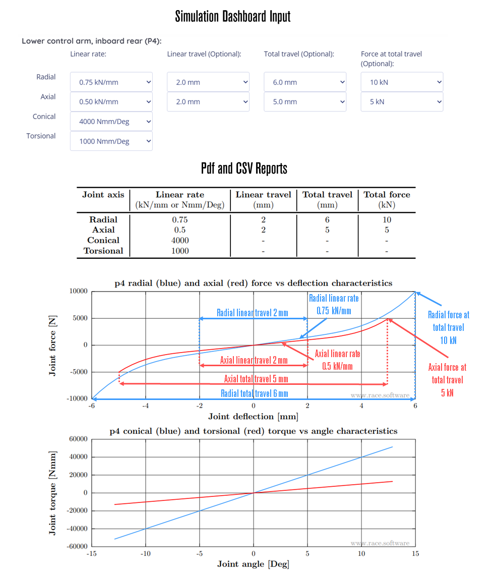 Figure 4. RACE Software Advanced – Non-linear Bush/Joint Definition Example
Defining the Suspension Topology
Each suspension type has a topology section where the user can customise the layout of their suspension. The topology section allows the user to select the part that dampers, springs and anti-roll bar drop links are attached to. For example, on a Double wishbone suspension the damper can be attached to the knuckle, lower control arm or upper control arm. The topology is selected using drop down boxes.
When selecting the topology, the relevant hardpoints must be realistic for the chosen attachment. For example, if the spring is specified as a coilover spring (spring sits over and is attached to the damper), the spring hardpoints must be on or close to the damper axis. Failure to have an aligned set of suspension hardpoints and suspension topology may cause some or all of the RACE simulations to fail.
Defining Tuning and Test Parameters
The tuning and test parameters section is used to define the tuning parts and test parameters for the suspension. Some or all of the following options are available depending on suspension type and RACE subscription level:
- Spring rate (N/mm): This is the rate or stiffness of the spring. It is measured in N/mm.
- Spring preload (N): This is the preload on the spring when it is installed in the suspension system when the suspension is in the position defined by the suspension hardpoints. This is also known as the fitted load. The corresponding fitted length is the distance between the spring upper and spring lower hardpoints and is calculated automatically from the suspension hardpoints. A worked example is given below to show how a spring preload can be calculated.
- Assuming a total vehicle mass of 1500 kg, 10% of which is unsprung mass, the total sprung mass (mass carried by the springs) is therefore 1350 kg. If the vehicle has a 50/50 mass distribution, then a single axle mass is 675 kg and a corner mass is 337.5 kg. Expressed as a force the corner weight is 3311 N. If the spring motion ratio is 0.7, then the spring preload is 3311/0.7 = 4730 N.
- ARB rate (Nmm/Deg): This is the torsional rate of the anti-roll bar. The anti-roll in RACE is modelled using two parts. A left part and a right part. The parts are joined using a torsional spring which sits between the left P61 coordinate and the right P61 coordinate at the x, y, z coordinate P61x, 0, P61z. The ARB rate entered here is applied as the rate of the torsional spring between the left and right parts of the anti-roll bar. The anti-roll bar parts themselves are rigid elements. This is only available in RACE Advanced.

Figure 5. RACE Software Advanced – Anti-roll Bar Diagram
- Tyre loaded radius (mm): This is the static radius of the tyre in its loaded condition. It is measured from the ground to the centre of the wheel. The tyre loaded radius is used to determine where tyre contact patch inputs should be applied during the suspension kinematics and compliance tests run by RACE.
- Wheelbase (mm): This is the wheelbase of the vehicle and is used to calculate ackermann characteristics for the steering system.
- Max steering rack travel – from centre (mm): This defines the amount of steering rack travel in the suspension system. It is the rack travel to get from a straight ahead steering position to full steering lock. It is always a positive value. This is available in RACE Advanced for suspension systems which can be steered.
- Ride height adjustment, +ve bump, -ve rebound (mm): This is used to define the ride height at which the kinematics and compliance analysis is run. The zero ride height (0mm adjustment) is the position at which the hardpoints have been entered. Positive ride height values lower the suspension (put the wheel into bump/jounce). Negative values raise the suspension (put the wheel into rebound/droop). The suspension must be capable of achieving the ride height entered or the simulation may fail. This is only available in RACE Advanced.
Static Toe and Camber Adjustment (Advanced only)
Static toe and static camber can be adjusted in RACE by defining the wheel rotation axis direction. The wheel rotation axis is defined by two hardpoints, P9 (wheel centre) and a second hardpoint outboard of wheel centre (P20). The wheel rotation axis is along a line joining P9 and P20. For a given P20 y coordinate, static toe is controlled by the x coordinate of P20 and static camber is controlled by the z coordinate of P20. The wheel rotation axis definition is shown below.
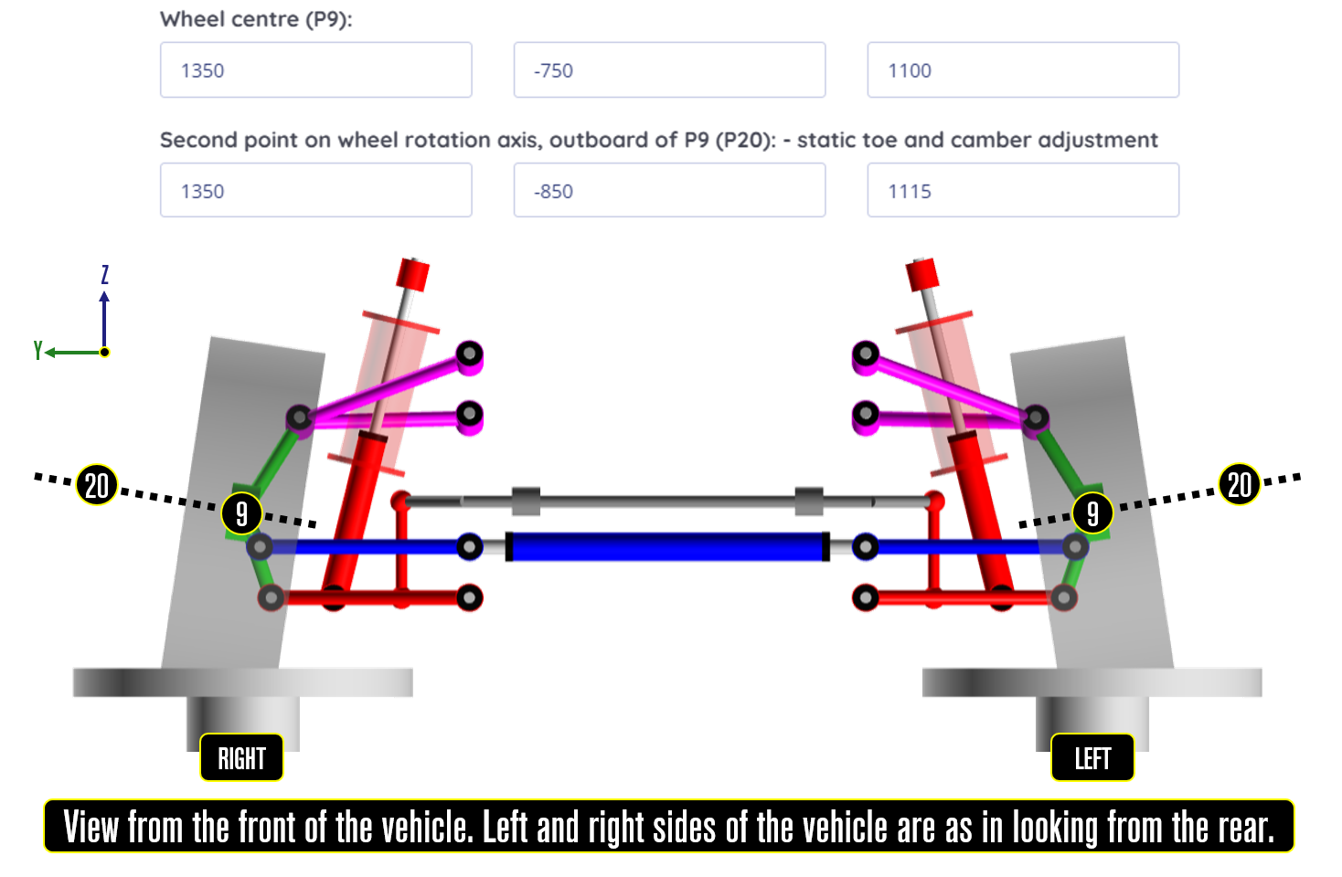 Figure 6. RACE Software Advanced – Camber Adjustment
Troubleshooting
When populating the input template, RACE runs validation checks on the data entered. If there is a potential issue with the data, RACE will generate an error or a warning when the user clicks ‘Submit and run simulation’.
- Errors are generated if there is an issue which will cause the simulation to fail. This could be a missing input field such as a hardpoint coordinate for example. An error message will be displayed which shows the source of the error. The user must correct the error and re-submit the analysis.
- Warnings are generated if there is an issue which may cause the simulation to fail. If a warning is generated, a message will be displayed which shows the source of the warning. The user has two options for warnings, either correct the data causing the warning or override the warning and submit anyway.
As with any simulation and analysis activity, failed simulations are a possibility in RACE. The validation checks aim to minimise the chances of this happening but a suspension which passes all validation checks can still fail one or more of the kinematics and compliance simulations (RACE Standard runs 6 kinematics and compliance test events, RACE Advanced runs 7). For example, if you specify a suspension with a very short steering arm on the knuckle, the steering test event will fail because the steering geometry will be infeasible and not able to reach the full rack travel. If less than 3 of the kinematics and compliance test events fail, a key performance indicator report will still be generated but without the results from the failed tests. If more than 3 test events fail an error report is generated showing the simulation inputs to help the user debug the issue.
Explainer Videos
RACE Software – Double Wishbone Demo Simulation – STANDARD Level – MBS / MBD K&C Analysis
RACE Software – Double Wishbone Demo Simulation – ADVANCED Level – MBS / MBD K&C Analysis