The E-Type is a sight to behold. It has well and truly cemented itself in the motorcar hall of fame for its beautiful lines, the universally acclaimed design and the legend around its inception, development, testing and launch.
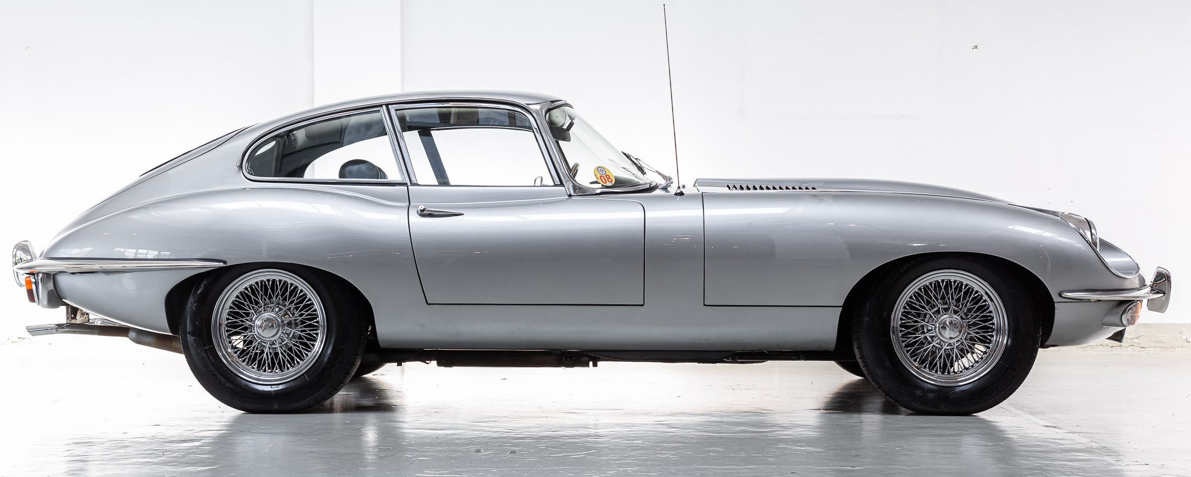
Figure 1. Jaguar E-Type (or XK-E in the US)
Superseding the XK-150 which was an evolution of the XK-120, the E-Type looked nothing like them, the E-Type’s brief was not just to succeed an existing Jaguar in its early line-up but to take a fresh look at car design in that era. The D-type race car was perhaps a lot more influential to the mood board perhaps used by the designers at the time than the XKs. The E-Type still features prominently in many an auction event and is on the top of list of collectors’ bucket lists. Enzo Ferrari called it the most beautiful car in the world.
Clive and Peter: How hard can it be?!
Clive Roberts and Peter Seear have been friends for over 50 years since their first week at Lanchester Polytechnic (now Coventry University), the city closest to the spiritual home of the E-Type. Clive lives in Thailand while Peter in Australia. They decide to re-engineer the timeless icon that is the E-Type to make what they think a bunch of enthusiastic Jaguar engineers might have done to it in the 1980s as a project car – prompted by the introduction of the AJ6 engine and with the aim of refreshing the dynamics.
No pressure then…!
The changes are not skin-deep. In fact, au contraire. They would like to keep the looks similar and want to overhaul the performance substantially. They are very clear that while the E-Type may be one of the most important cars to the British Motor Industry’s history, its dynamics could do with the same attention its appearance rightly deserves.
Enter RACE Software.
RACE Software, the world’s first cloud-based multibody simulation service enables Clive, Peter, and many others around the world to take up challenges like this and more. It combines model build, model parameterization, post-process, data storage, and report generation into a single platform. It is cloud-based, requires no software installation, and can be run from a web browser on any computer, phone or tablet.
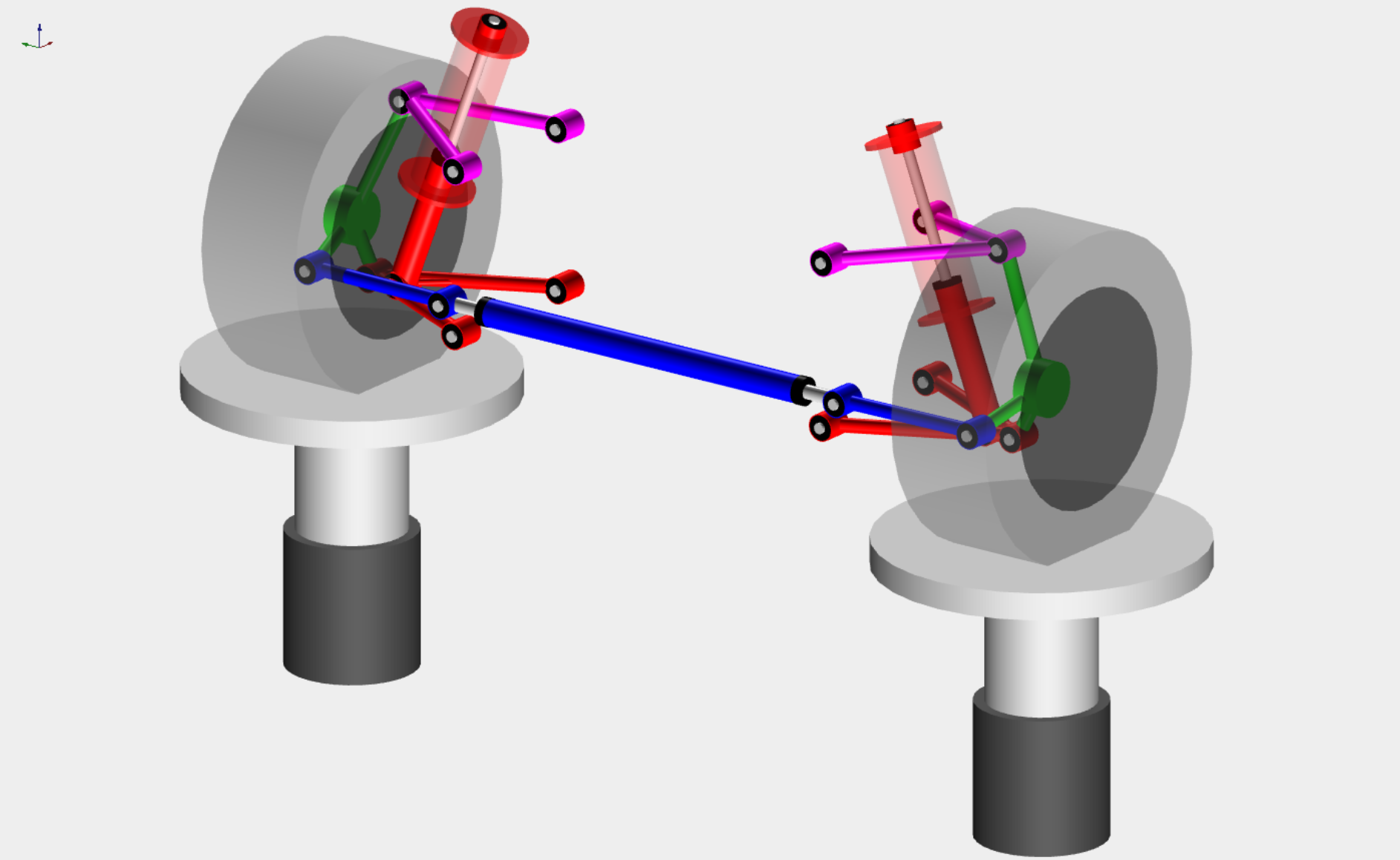
Figure 2. 3D representation of a standard suspension setup – Graphics are rendered in real time on RACE Software platform based on inputs from the user
RACE enabled Clive and Peter to not only iterate rapidly to develop a superior suspension system but also understand the reasons and justifications for alternative approaches. This is because RACE Software understands the fact that comparing variables and the subsequent resulting KPIs are an inherent part of engineering development.
The idea that two friends living in two continents without a deeply involved engineering team and highly available and performant cluster computer capable of running simulations can just take up the challenge of re-engineering the whole suspension system is testament to the mission of RACE Software. Cloud computing and the advent of SaaS solutions across the engineering industry provides this opportunity.

Figure 3. Clive Roberts testimonial
This novel approach moves the focus to the analysis results and away from the multibody simulations (MBS) software. The value add in any chassis design process comes from using the simulation results to make design decisions. There is no value add from the building of an MBS model, this is typically essential non-value add. The cloud approach completely removes this non-value add activity and allows the designer to focus on the analysis of the results to improve their design.
What’s new with THIS E-Type project?
They see distinct differences between their project and the numerous modified E-Type projects available in the market. Others typically offer a lot of cosmetic work but very little engineering change from the original. They’re taking a different approach, concentrating on technical updates. They want to expand the performance diagram while keeping the grace for which the E-Type is famous. The Jaglovers forum and their members have also been of great support.
Their design approach was to take the structural foundations of the E-Type as their starting point and design a 100% new suspension system taking advantage of the RACE program to analyse hundreds of geometry permutations. To do this they started by measuring the available space and producing first pass designs on a drawing board.

Figure 4. Front suspension hand drawing design layout
It was very clear from the outset that the suspension nodes/hard points were offset from structural nodes/hard points and this was less than ideal for rigidity. Using the track width and 6.5” wire wheels available they set targets for Scrub Radius, KPI and created a base suspension layout that was closely aligned with chassis structural nodes/hard points. Figure 4 shows the first pencil drawing of their design layout overlaid with the standard E-Type suspension.
Clive then modelled many sets of geometry which accommodated the large 310mm AP Racing ventilated discs and four pot calipers within the real estate available.
Using RACE Software, once Clive had determined the best geometry they could achieve within the available space the designs were put into CAD so billet uprights could be designed and FEA analysis carried out.
Once parts were detail designed in CAD, they looked for an expert CNC business that was prepared to make their bespoke parts. They found the ideal partner Alex from BryPar in Campbelltown, New South Wales who makes billet aluminium uprights for many car makes and racers and was a great support in making their design machinable with subtle changes to surfaces. The end results were very gratifying, even though the uprights are out of sight, they must be to the highest standard of engineering possible.

Figure 5. Rear Knuckle/upright from Design to Manufacturing
In addition to making unique parts of their own design they worked with some great suppliers who make custom specialist parts. One of the key items to get right is steering feel and geometry and this was only possible by having a custom steering rack made to the geometry determined from the RACE analysis by Titan of England.
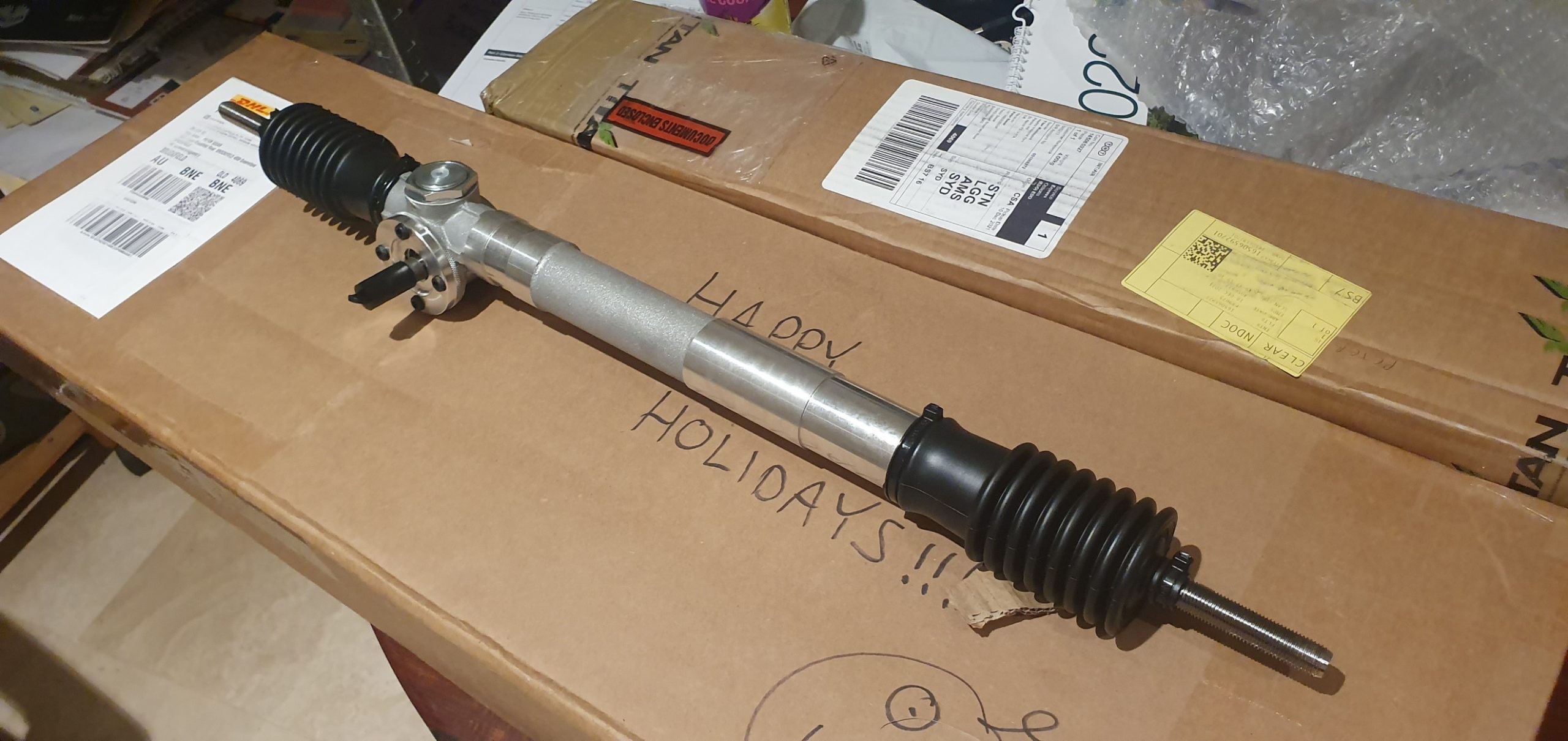
Figure 6. Custom steering rack based on recommendations from RACE Software reports
Working with Quantum of England based on Clive’s geometry and performance curves from RACE Software reports custom made damper coilovers have been engineered.
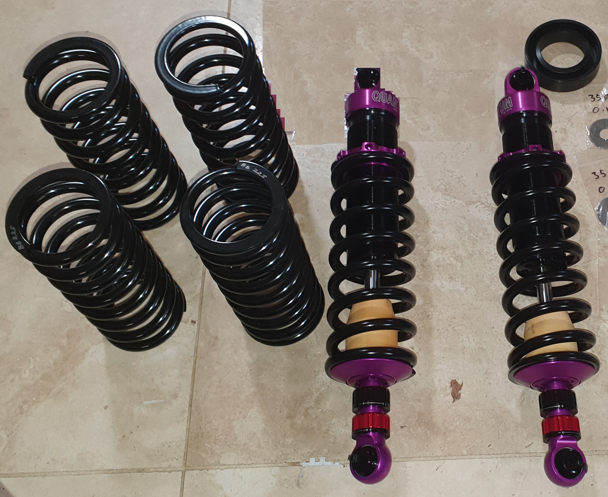
Figure 7. Custom springs and dampers were specified based using RACE Software reports
Clive found a convenient damper test facility, BDR in Bangkok, and managed to get valuable pre-driving test work done testing the adjustability of the Quantum dampers. Patrick of Quantum supplied many internal parts so that Clive could strip and reassemble the dampers and generate performance curves.
It became obvious early in the project that a new suspension design would necessitate substantial structural modifications. The hand drawing below details the more important changes made. Essentially, they set out to make the torsional stiffness an order of magnitude stronger than the 1964 E-type that their car is based on. Bearing in mind that they are building a S1 Coupe to start but Clive is now planning to build a S1 drop head (open two seater OTS), they wanted to improve a number of other structural areas such as:
- Provide a measure of side impact protection
- Increase bending and torsional strength
- Integrate a roll structure with the monocoque
- Integrate the front tubular structure with seamless load paths into the monocoque
- Provide real estate for a rear suspension where space is a real premium due to the standard E-Type using a drive shaft as the upper suspension arm. Creating space for a double wishbone meant chassis surgery.
- Provide a safe, protected area for the petrol tank inside the chassis legs
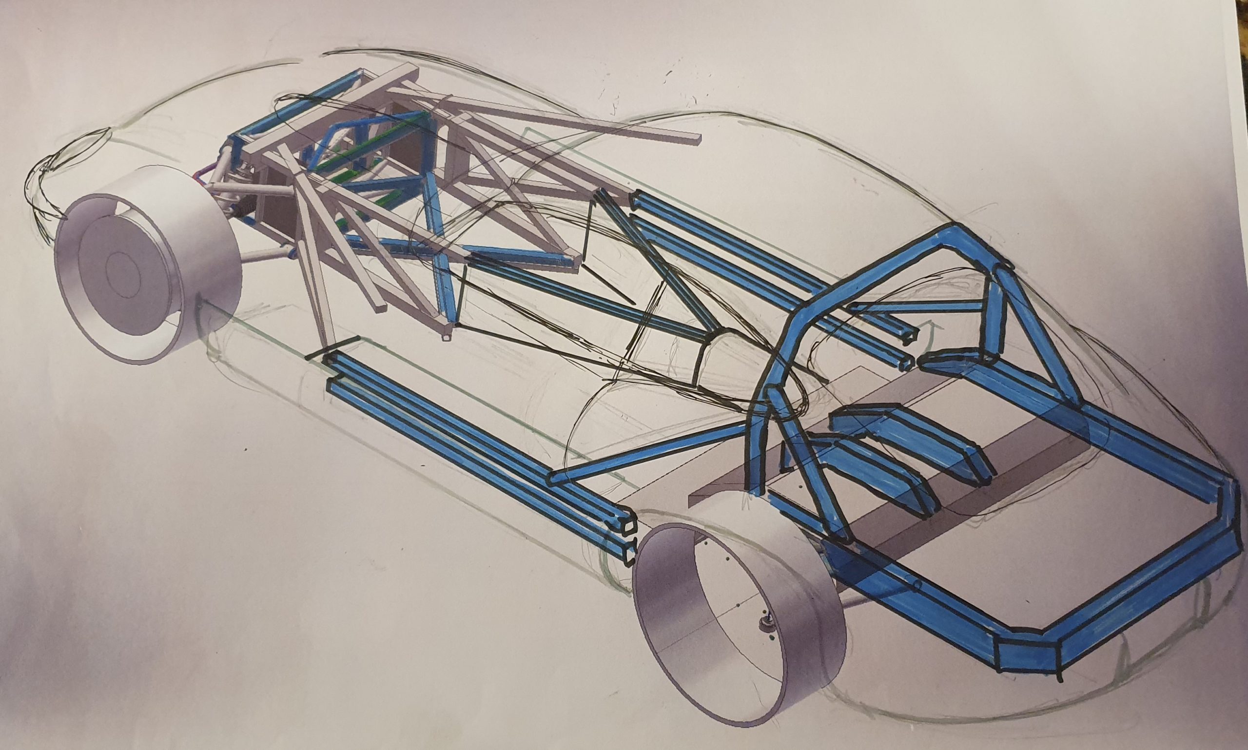
Figure 8. A hand drawing of the structural changes for the E-Type’s chassis
The rear suspension was designed by creating an integrated pair of chassis rails above the rear suspension cross tunnel. Two further chassis rails were added that carry the transmission tunnel loads across the lateral tunnel. The rear suspension is a non-removable frame welded as an integral element of the monocoque. The transmission tunnel was replaced with a tubular structural member that now transmit the front space frame loads into the monocoque while providing a substantial increase in bending strength.
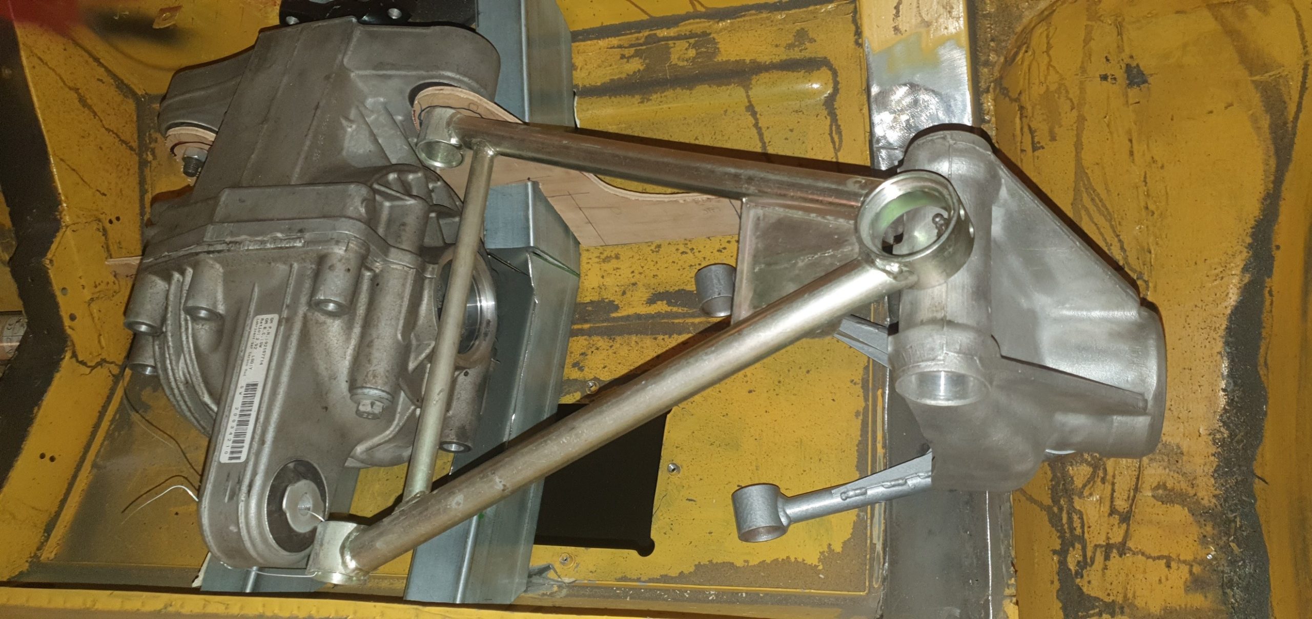
Figure 9. Early rear suspension mockup
The photo above shows an early mock up with Lotus Elise wishbones, E-Type upright and aluminium ZF differential. All in all, a substantial weight saving. They have designed custom tubular wishbones and uprights. The depth of the outer chassis rails has been reduced and a greater section modulus RHS chassis beam has been integrated into the topside of the boot floor. After surgery the section modulus has doubled and has also allowed the roll cage structure to be integrated with the monocoque.
The car has substantial weight saving afforded by the aluminium AJ6 engine, aluminium bonnet, doors, tailgate, ZF aluminium differential housing, replacement of trim with far more spartan trim levels, aluminium radiator, seats, lightweight chrome-moly tubular wishbones, 2 lightweight rear coilovers in place of 4, aluminium petrol tank and more. They have added approximately 22kg of additional structural members and a 19kg roll cage structure. Netting off the weight savings and additions indicates the finished weight is expected to be 110kg lighter than its 1964 self.
They set out to achieve the best accuracy when fabricating new suspension parts and chassis pivot points, so decided to have the suspension geometry nodes/hard points located by “self-jigging” kits of plates cut using high pressure water jet cutting. This ensures the suspension geometry will be accurate to within a fraction of a mm while making the structure self-jigged while assembling and welding.
Water jet cutting does not distort the 1.8mm steel plate and makes self-jigging tabs easy to incorporate into the parts kit.

Figure 10. Manufactured parts using water jet cutting
Front picture frame replaced with new spaceframe which FEA indicates is 450% stiffer in torsion than standard. Critically FEA analysis has allowed the torsion bar suspension to be replaced with coil springs. Dampers loads make up a substantial portion of the loads placed into the spaceframe and thus the move from torsion bars to coil springs was less radical than it first appeared. Many debates have run over the years about the replacement of torsion bars with coils and they set out to determine what loads were imposed and how best to handle those loads while not radically altering the front frames. The FEA highlighted that the front frame diagonals can be reversed to benefit. The appearance remains similar but the diagonals are now predominantly in tension rather than compression in most load cases. They took the opportunity to change load paths, structural attachment points to the monocoque and add diagonals under the engine. Changing from torsion bars with torque reaction handled at the bulkhead by a cross member was analysed and as a result the front frames were strengthened by an order of magnitude through detailed attention to structural nodes/hard points, adding stiffness at the bulkhead attachment points and detailed changes to the diagonals.
In addition to water jet cutting and CNC 5 axis machining they experimented with 3D printing aluminium cam covers as an experiment on a non-safety critical part. They will report back on accuracy and surface finish in a later article, but the process so far has been a simple CAD file design emailed to an aluminium 3D printer 4000km away and they are waiting for the first parts to arrive in Brisbane.
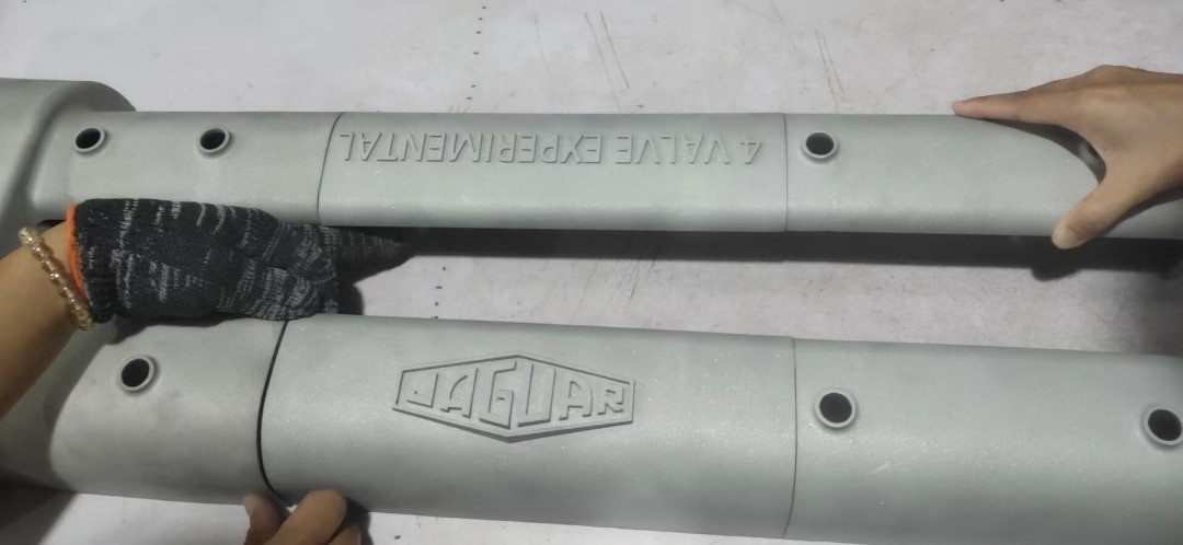
Figure 11. Experimental 3D aluminium printing of cam covers
What’s next?
Suspension and powertrain components are fully designed, parts are being made and arriving daily. Peter is assembling it to a rolling vehicle in Australia, with structure and major mechanical systems in place. Around mid 2023 they should be getting together to run it and set it up. They have done so much analysis of the structure and suspension that they are confident the base performance will be good, allowing them to move quickly to the tuning stage. They are a step ahead through running a matrix of damper tests at BDR.
They have run several hundred models on the RACE Software platform thoroughly mapping all the parameters to understand the limitations of the original system. So, changes abound! The suspension concept has completely changed front and rear, suspension parts are new and unique to this car.
While they have enormous respect for the team that created the original car, they do recognise the advantages that they have now:
- They can make sympathetic use of sixty years’ technology
- They have access to design and analysis tools such as RACE Software which didn’t exist then
- They’re only making a sports car, no need to compromise for other uses
- This is a private project, no need to adjust their targets to satisfy any other stakeholders
They have a host of suppliers from around the world including Australia, England, Bangkok, USA, and Germany lined up. We can’t wait to see their first prototype vehicle hitting the test track in USA in 2023. Clive and Peter have already started two new similar projects with RACE Software.
Being one of the early users to access some of the RACE Software’s features, Clive continues to provide expert inputs to the RACE development team drawing from his vast experience in the industry, while also learning from RACE’s educational courses.
The team at RACE value this relationship and will be sharing more such stories. As their team and ambitions grow, the capabilities of RACE Software that they use will be ready to grow too.

Figure 12. E-Type aesthetics