
1. Introduction
Suspension hardpoints (HPs), also referred to as nodes, are the 3D coordinates of all the key attachment and reference points that define a vehicle’s suspension geometry. Most of these are the “pick-up points” where arms, links, dampers, springs, anti-roll bars, steering links connect to the chassis, subframe, upright (knuckle), or each other. Others (such as the wheel centre) are reference points used to describe the suspension geometry.
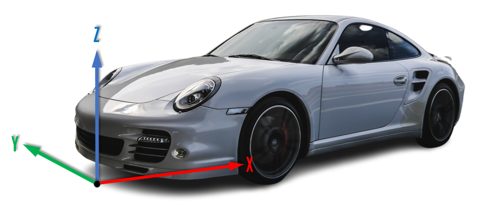
Hardpoints are mathematical points in space defined in a global coordinate system (X, Y, Z), such as:
• X: longitudinal (forward/backward)
• Y: lateral (left/right)
• Z: vertical (up/down)
This article describes how to measure the suspension hardpoints on a vehicle. You can also learn more about the impact of suspension hardpoint accuracy on suspension performance in this article: Impact of Suspension Hardpoint Accuracy on Suspension Performance
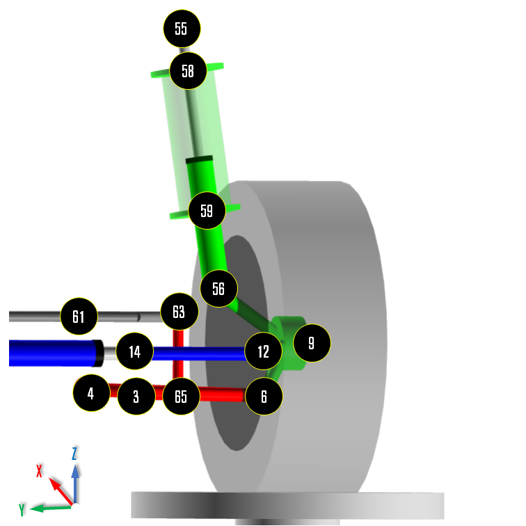
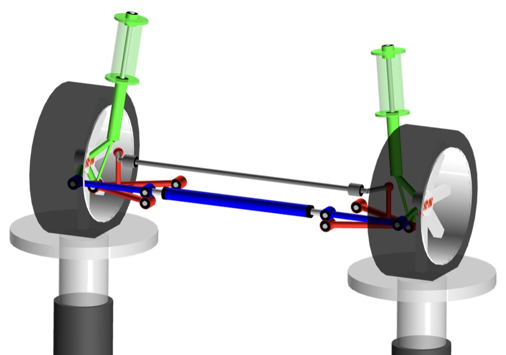
MacPherson Suspension HPs (Left Wheel/Front View) – Example
2. Vehicle preparation
A. Set the vehicle in the target condition
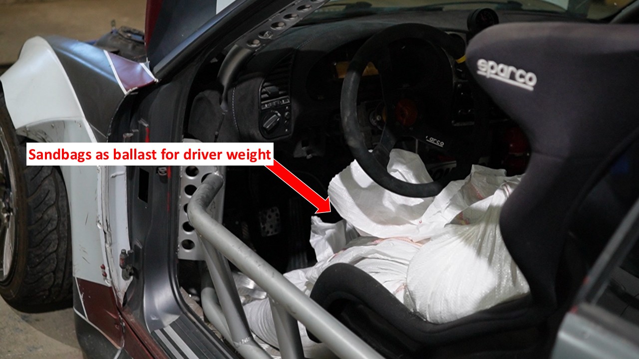
Set the vehicle on a level surface and load it to the desired condition (fuel level, fluids, driver/passenger and luggage ballast as required).
Inflate the tyres to the correct pressure and make sure the suspension is settled and the steering is in the straight-ahead position.
Keep this load condition constant for all later measurements; if a driver, passengers or luggage are removed at any stage, replace them with equivalent ballast in the same locations so the vehicle HPs are always measured at the intended loading.
B. Measure the corner weights (OPTIONAL)
With the vehicle in the prepared condition from step A, place each wheel on a scale on a level, flat surface. Bounce the car lightly at each corner to settle the suspension and release any bush/joint pre-load, then record the total mass and the weight at each corner. If you do not have four scales, measure the front and rear axles separately, making sure the other axle is supported at the same height (for example, on blocks the same thickness as the scales) when you take each measurement.
This step is optional, but it helps you understand how the vehicle load is distributed at each corner and can later be used to calculate the correct spring preload (see “Defining Tuning and Test Parameters“).

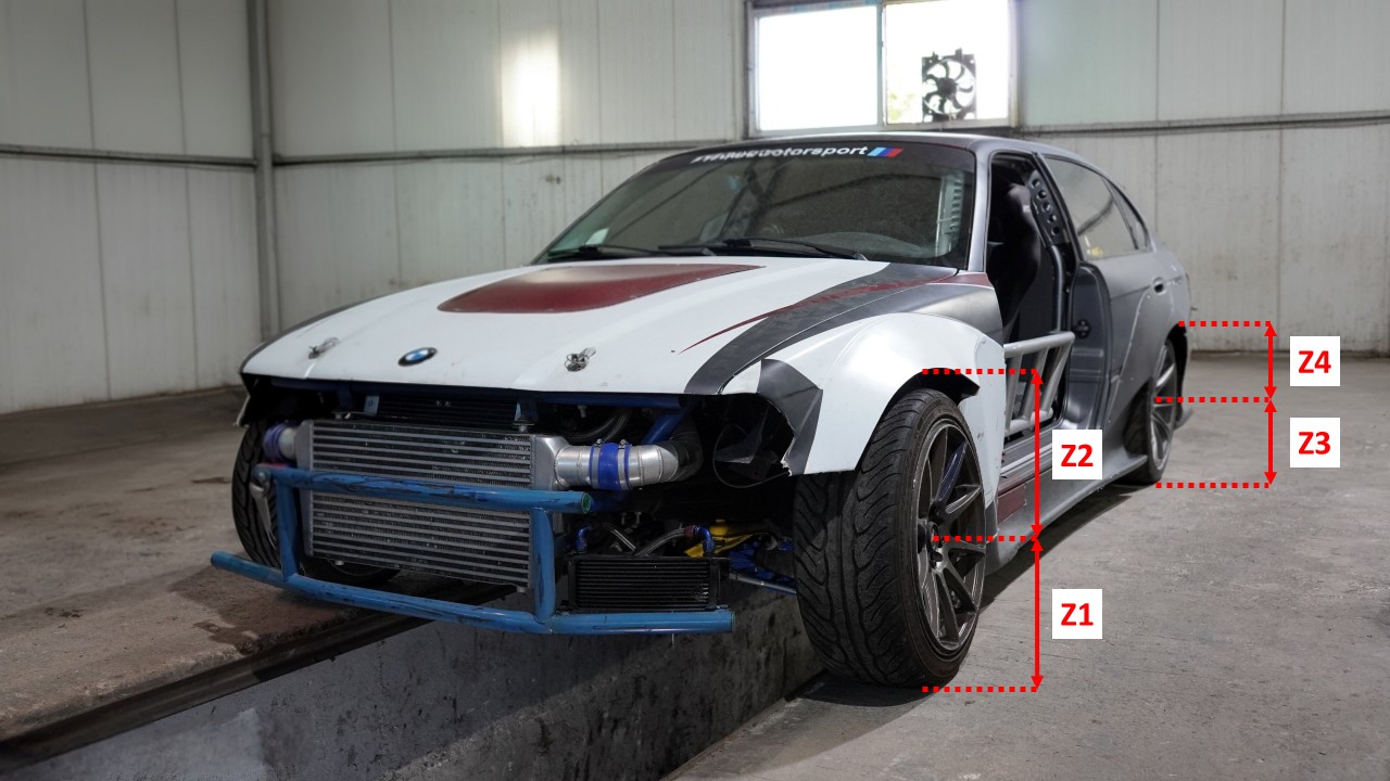
C. Record ride height
With the vehicle on its wheels in the prepared condition from step A, bounce it a few times at each corner to settle the suspension and remove any preload in the joints/bushes. Then, for each corner you intend to measure (in most cases you can focus on the left-hand side only, i.e. front-left and rear-left wheels):
• Measure the vertical distance (Z1 & Z3) from the ground to the wheel centre.
• Measure the vertical distance (Z2 & Z4) from the wheel centre to the edge of the wing (fender) or other reference point.
Record these values for each measured corner.
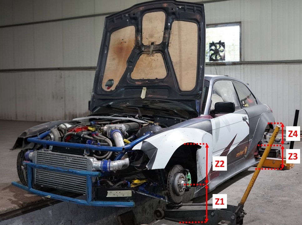
D. Wheel removal and access
Remove the front-left wheel (and the rear-left wheel as well if you are going to measure the rear suspension). If needed, remove any local bodywork or liners to gain access to the suspension joints and reference points where you will measure the HPs. Support the vehicle safely with a jack and axle stands under the suspension and adjust the height so that the hub/wheel centre sits at the same vertical position as in step C (i.e. the same distances you recorded there – Z1, Z2, Z3, Z4 from ground to wheel centre and from wheel centre to the wing/fender). Keep the vehicle load (ballast, fuel, etc.) unchanged while doing this.
3. Measurement methods
Before looking at each method, define a common (global) coordinate system that will be used for all measurements.
Set the origin (0, 0, 0) on the ground at the centre of the front bumper, on the vehicle centreline (front-most point of the vehicle projected vertically down to the floor).
Use the following convention:
• X: longitudinal –> positive X towards the back of the vehicle (values increase as you move rearwards).
• Y: lateral –> negative Y towards the left-hand side of the vehicle (with Y = 0 on the vehicle centreline).
• Z: vertical –> positive Z upwards from the ground.
Mark the origin and centreline on the floor so all measurements can be related back to this system. This coordinate system applies to all measurement methods described below.
A. Manual measurement (DIY)
You shall use a combination of plumb-bob, tape, height gauge and caliper.
For each joint or reference point, hang a plumb-bob from the point and mark where it touches the floor.
Measure X and Y on the floor from the origin at the front bumper and the vehicle centreline to each mark.
Measure Z as the vertical distance from the joint down to the floor (using a ruler/height gauge), and use calipers to locate bore centres for bushes and ball joints where needed.
This method will be less accurate but low cost and workable in most workshops when no coordinate measuring machine (CMM) arm or 3D scanner is available.
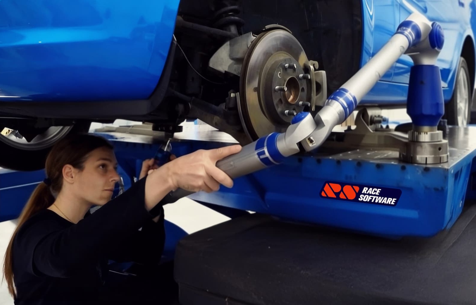
B. Coordinate measuring arm
Mount the measuring arm on a rigid base and register it to your global coordinate system (0,0,0 at the front bumper on the floor, same XYZ directions).
Touch the probe head on each suspension joint and reference point.
Let the arm software record the X, Y, Z coordinates and export them as a table or CSV.
This is much faster and more repeatable than the manual method and is ideal if you have access to a measuring arm.
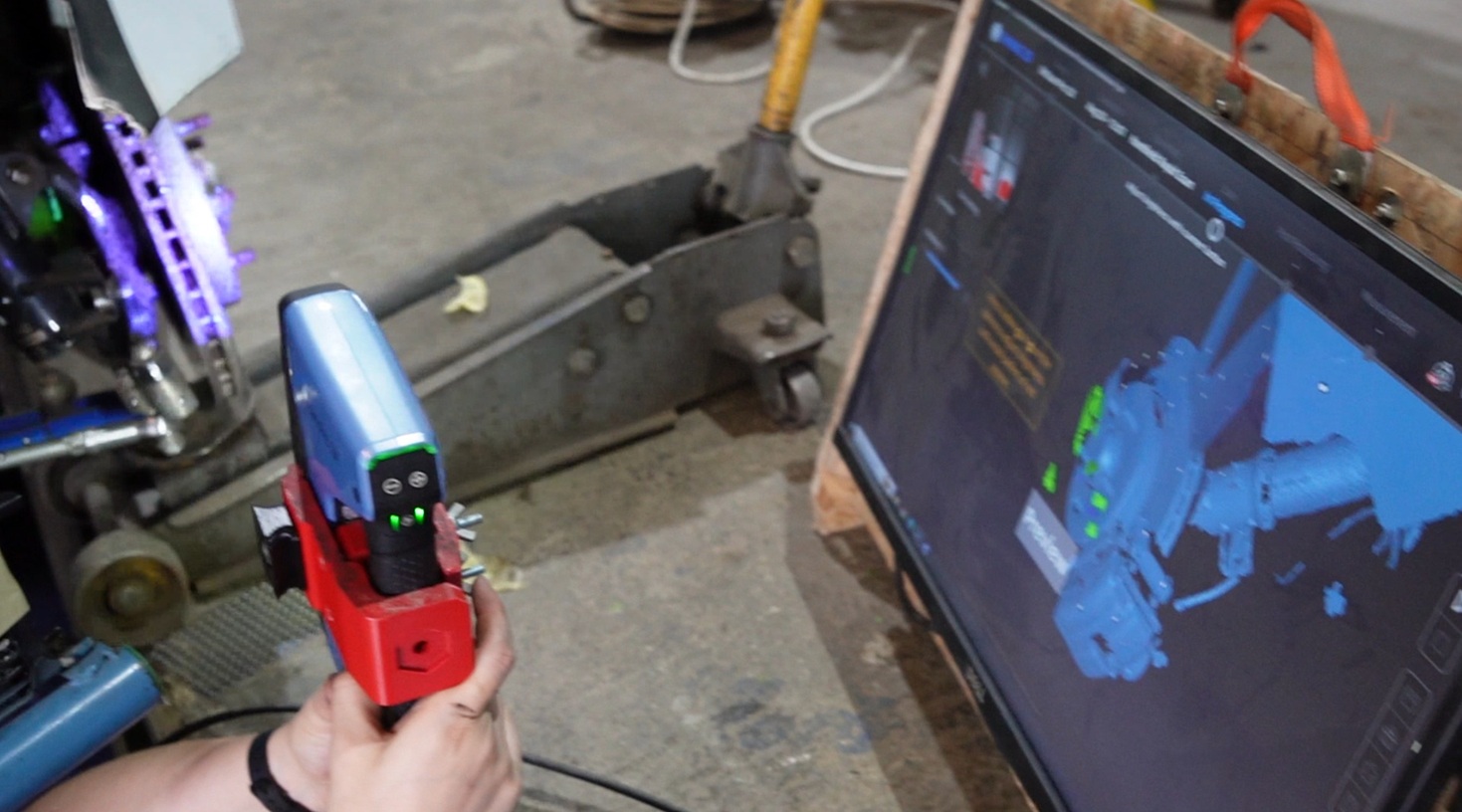
C. 3D scanning / photogrammetry
Apply markers or targets to the joints, reference points and other car components you want to capture.
Scan the suspension area with a 3D scanner or take a calibrated photo set for photogrammetry.
In the processing software, align the model to your global coordinate system (same origin and axes) and read off the XYZ coordinates of each marker.
This is powerful for complex geometry, but requires more post-processing time.
4. Processing measurements into HP coordinates
Whatever measurement method you use, the next step is to reverse engineer the HPs from the measured geometry and express them as coordinates in the global XYZ system.
You always measure surfaces, but need the geometric centres of joints/bushes and reference points. Think of this as fitting simple shapes (sphere, cylinder, circle, plane) to the measured data.
Ball joints
• Manual: use calipers to find the ball centre relative to accessible surfaces, then translate that into X, Y, Z.
• Coordinate measuring arm / 3D scan: pick several points on the spherical surface and use a “fit sphere” function. The centre of that sphere is the HP.
Bushes, sleeves and through-bolts
Treat the bush housing as a cylinder.
• Manual: measure diameters and offsets, then construct the cylinder centreline by hand or in CAD and find the mid point.
• Coordinate measuring arm / 3D scan: pick points around bush/bush housing and use a “fit cylinder” function to determine the rotation point.
The cylinder centreline gives the joint axis; the HP is the centre of the inner hole at the relevant axial position.
Where bushes can be hard to access use a similar method for the brackets, sleeves or the through-bolts.
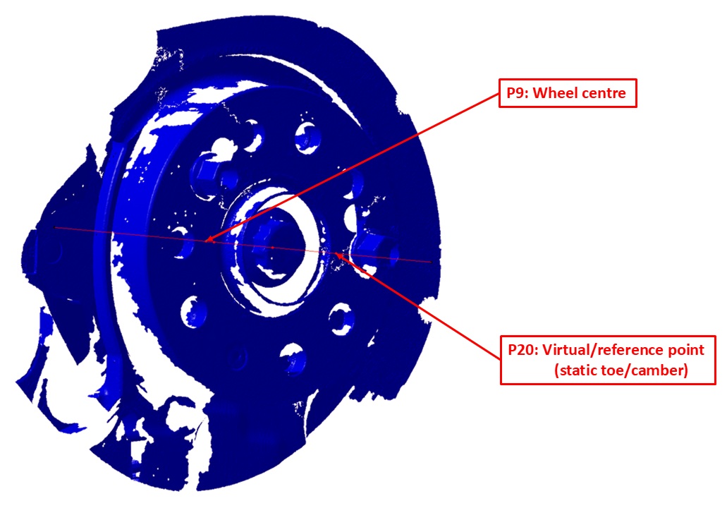
Wheel and hub reference points (for wheel centre, toe and camber)
Find the hub axis and mounting face:
• Measure points on the hub inner hole/ bolt circle and use a “fit circle/cylinder” to get the hub axis.
• Measure points on the hub mounting face / brake disc and fit a plane.
• The intersection of this plane with the hub axis gives a robust hub reference point.
Construct the wheel centre using rim data and ET/ETA:
• From the wheel specification (rim width, ET/ETA/offset), define the wheel centre along the hub axis.
• Start from the hub mounting face and move along the hub axis according to the rim half-width and ET/ETA so that you land at the geometric wheel centre.
• Record this wheel-centre point as a HP (X, Y, Z).
Define an outboard point for toe and camber:
• Using the same hub axis and wheel geometry (rim width, tyre radius), construct a second (virtual) point on the outer side of the wheel/tyre, offset from the wheel centre.
• The line between the wheel centre and this outboard point defines the wheel plane in space for toe and camber angles in the global coordinate system.
 Exporting HPs to CSV
Once you have finished the reverse engineering, collect all HPs and the reference (virtual) point for toe/camber (P20 in RACE Software) into a single table with one hardpoint per line in the format:
hardpoint_name, X, Y, Z
For example, for a hardpoint P4 on the front-left corner (left-hand side is negative Y):
P4, 100, -400, 300
Make sure the coordinates follow the same global convention defined earlier (X positive rearwards, Y negative to the left, Z positive upwards). Save this table as a CSV file. You can then import the CSV with the HPs directly into RACE Software using the hardpoint import function. The left hand side of the suspension will be mirrored to the right and the complete axle will be generated.
MacPherson suspension RACE Software Advanced – Example