This post looks at tuning linked key performance indicators (KPIs) using RACE software. Linked KPIs are KPIs where tuning one in isolation directly impacts one or more other KPIs. The example used in this post is tuning bump camber and roll centre height on a double wishbone suspension system.
These KPIs are tuned using the front view angle of the upper control arm (UCA) and lower control arm (LCA) as shown in the simplified diagram below. The amount of bump camber in the suspension is determined by the distance between the camber pole and the wheel centre line. The closer the camber pole is to wheel centre, the more bump camber in the suspension. The roll centre height is the height of the intersection of a line joining the contact patch and the camber pole with the centre line of the vehicle, as shown below.

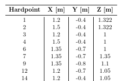
In this example a simple double wishbone layout is used. The suspension hardpoints used for the baseline tune are shown below. The hardpoint numbers follow a common convention used in the automotive industry. 1 and 2 are the UCA inner hardpoints, 7 is the UCA ball joint. 3 and 4 are the LCA inner hardpoints and 6 is the LCA ball joint. 9 is the wheel centre. 12 and 14 are the track rod outer and inner ball joints , respectively.

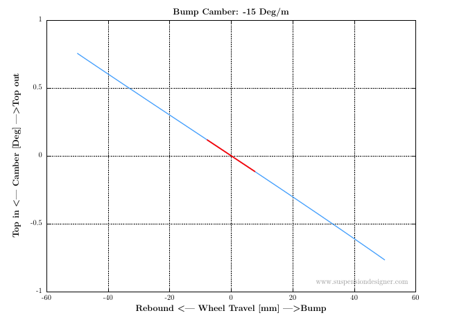
In this tuning example, the target bump camber range is -20 to -22 Deg/m with a target roll centre height between 80-90mm. The baseline suspension tune was analysed using RACE software and the bump camber curve from the RACE pdf report is shown below. The baseline bump camber is -15 Deg/m and is below the target range. The roll centre height for this design is 85mm and is in the target range. As the bump camber is too low, the first iteration of tuning will look at the impact of changing the UCA angle in front view. From the diagram above, to increase bump camber we need to move the camber pole closer to wheel centre, this is achieved by dropping hardpoints 1 and 2 to increase the angle of the UCA.

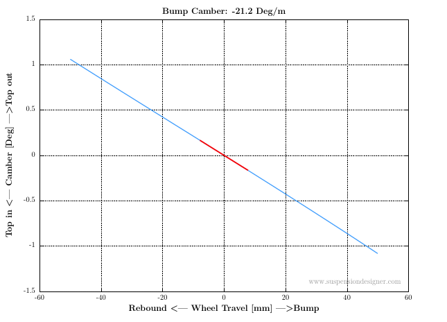
For this first tuning iteration, hardpoints 1 and 2 are dropped by 12mm in z. The resulting bump camber curve is shown below. The bump camber is -21.2 Deg/m and is in target. This tuning iteration was done with no regard for the impact on other KPIs. In this case, the roll centre height has now increased to 120mm. As these KPIs are linked, tuning bump camber with just the UCA will always have a knock on effect on roll centre height. Although not explored here, the same would be true for tuning with just the LCA. The key to meeting both targets is to tune both the positions of the UCA and LCA together.

For the second tuning iteration, the impact on roll centre height is monitored as bump camber is tuned. Following some sensitivity studies on both the UCA and LCA inboard hardpoints, the hardpoints required to achieve both target were found. On the UCA a 19mm drop in hardpoints 1 and 2 was required. From the first tuning iteration, we know that this will overshoot the bump camber target and also give a roll centre height greater than 120mm. On the LCA, hardpoint 4 is dropped by 13mm. This hardpoint drop reduces both bump camber and roll centre height. The combined effect of the hardpoint moves above give the bump camber curve shown below with a roll centre height of 88mm, so both are now in their target ranges.

This article demonstrates a simple example of how KPIs can be linked. When tuning linked KPIs, the impact of any hardpoint or bush tune on all linked KPIs must be monitored. The hardpoint tune in the first tuning iteration above was intentionally done to demonstrate the impact of ignoring a linked KPI when tuning.
All analysis and results shown here were quickly and easily generated using RACE software. The example was intentionally kept simple to demonstrate the principle of tuning linked KPIs. This article is the second post in the suspensiondesigner.com suspension tuning series. The tuning series is intended to demonstrate the process of tuning specific KPIs of a suspension system.
