Kinematic wheel centre recession is a measure of the longitudinal motion of the wheel centre when the suspension travels into bump. The metric is measured in millimetres of wheel recession (rearward longitudinal motion) per metre of wheel travel, mm/m.
A positive value for this KPI indicates that the wheel travels rearwards as the wheel moves into bump. This is a desirable situation from a ride comfort point of view but is not always possible as kinematic wheel centre recession is linked with other KPIs and as a result must be tuned carefully. The amount of kinematic recession in a suspension system is determined by the position of the longitudinal pole or castor pole as shown below.
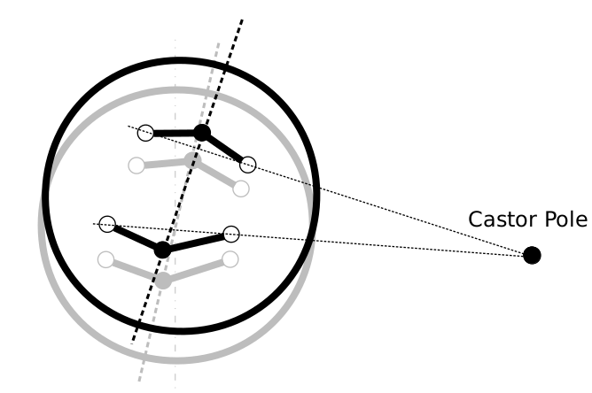
Both the vertical height and longitudinal position of the castor pole relative to wheel centre are key. If the castor pole is below wheel centre in side view, the wheel will exhibit kinematic recession and travel rearwards in bump. If the castor pole is above wheel centre in side view, the wheel will have kinematic precession and travel forwards with suspension bump. For a given pole height, the amount of kinematic recession (or precession) is governed by the longitudinal distance between the castor pole and the wheel centre.
To understand the impact of this KPI on ride, consider the analogy of a wheel barrow traversing an obstacle. If you try to push a wheel barrow forwards over an obstacle, the wheel barrow hinges about the handle bars (i.e. the castor pole is at your hands) and the wheel has kinematic precession (i.e. forward longitudinal motion in bump) . In this case, when the wheel hits the obstacle, it must push into the obstacle as it moves upwards and over the obstacle. The user feels an impact force through the wheel barrow handles. Now consider the scenario where you pull the wheel barrow over the same obstacle, The wheel of the barrow now exhibits kinematic recession (i.e. rearwards longitudinal motion in bump). In this case, the wheel moves away from the obstacle as the wheel moves upwards and over the obstacle. The result is reduced force into the hands of the user compared with the first scenario. Achieving the ride comfort benefits of kinematic wheel centre recession demonstrated with the wheelbarrow analogy must be balanced against the impact on other KPIs, namely bump castor and anti-properties.
The closer the castor pole is to wheel centre in side view, the more wheel recession (or precession) the suspension will have for a given bump motion. The downside is that this will also increase bump castor. On a steered suspension, high levels of bump castor can have a detrimental affect on steering feedback (as discussed in the posts on static castor and bump castor).
Under traction for driven suspensions, if the castor pole is above wheel centre the suspension will exhibit anti-lift (front suspension) and anti-squat (rear suspension), if the castor pole is below wheel centre the suspension will exhibit pro-lift and pro-squat. As an example of the compromise the designer faces, consider the front suspension of a typical four wheel drive production vehicle. The designer would ideally like some kinematic wheel centre recession to improve ride comfort and also some anti-lift to improve body control under hard acceleration. These are conflicting goals and would be difficult to achieve using conventional suspension designs.
As is the case with many suspension design decisions, the right balance for these KPIs depends on the application for which the suspension is being designed. For a track car, ride comfort would not be a priority so bump castor could be minimised to ensure consistent steering feedback to the driver with suspension travel. For a high powered four wheel drive vehicle with high centre of gravity (e.g. SUV), anti-lift under acceleration may take priority. For an on-road sports car, some level of ride comfort may be needed to ensure the car is enjoyable to drive over long distances on a daily basis.
—